

Falling is a major issue
A fall does not have a single victim. Rather, the loved ones to fall-susceptible people are burdened by their responsibility to look out for and protect this person in their lives.
In addition to the time and attention of loved ones, people falling also puts stress on emergency services, filling up their phone lines and thinning their available personnel at any given time.
There is a fear that comes with being alone when you are susceptible to falling. What if you fall and you are unable to reach a device that allows you to call for help?

My Grandparents
In shaping a user persona, I consulted with my own grandparents to evaluate how they live with falling.
My grandmother Is 91 years old and has Parkinson’s Disease. She falls frequently and sustains major injuries each time, having broken her neck, back, ribs, and wrist since receiving her Parkinson’s diagnosis two years ago. Notably, she receives black eyes from falling as well, resulting from Parkinson’s Disease interfering with her ability to reflexively cover her face or adjust herself while falling.
My grandfather is 90 years old and has become the primary caretaker for my grandmother. He is able-bodied aside from use of a cane, and he lives with my grandmother, alone in the house that she grew up in. His time is devoted to assisting my grandmother, but because of his age he is unable to pick her up from the ground after a fall. Each fall means a lift-assistance call to the fire department.
Considerations for the user
To guide the design process I established three core principles:
The design solution has to respect the lifestyle and ideals of the user: The user should be able to continue doing the things that bring them joy, with the design solution not impeding on their ability to wear the same clothes, sit in their favorite chair, etc. In the case of my grandmother, she is a very stylish woman and simply would not use a product that she found ugly or limited her ability to style herself.
The design solution needs to allow the user to retain autonomy: The user should continue to have a feeling of control and independence when using the design solution, rather than feel like the design solution is taking away from their humanity.
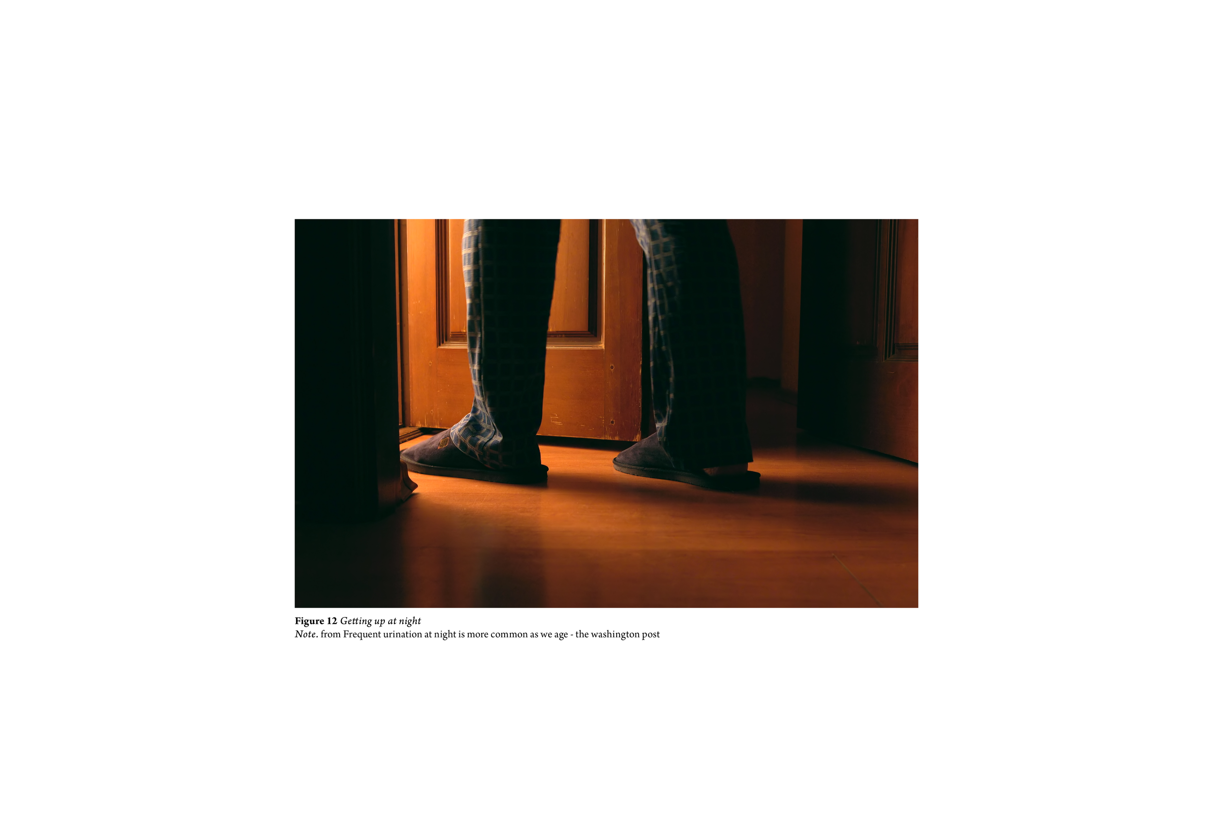
The design solution needs to be easy to equip: It is a common issue for elderly people that they wake up in the middle of the night with an urgent need to go to the bathroom. At this time, they are sleepy, in a rush, and in a poorly lit environment. To deal with scenarios like these, the design solution should either be easy to put on quickly or so nonintrusive that it never needs to be taken off.
Designing for prevention
Looking at the problems that the user faces, the solution that addresses the user entirely is a solution that designs for prevention of falls.
With the exception of mobility devices like walkers, every product on the market designed for falling is a protective device. These products accept falling as an inevitability, attempting only to mitigate the consequences of falling while serving as a reminder of unsolved vulnerability. Designing for prevention means empowering the user by solving the issue of falling entirely.
A device that prevents falling enables not only the safety of the user, but frees up the lives of those around the user. Loved ones no longer need to worry about the user as they are self-sufficient and won't need to be lifted up or driven to the hospital at a moment's notice. This also greatly lightens the load on emergency services.
Design Directions
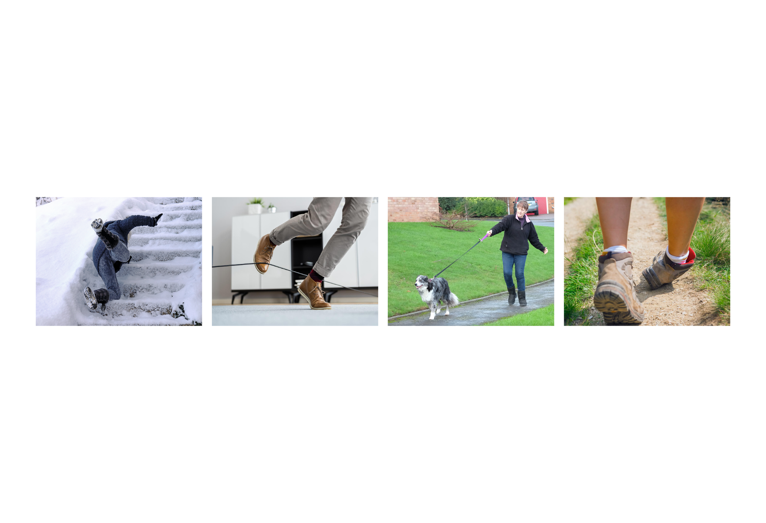
From researching the ways that able-bodied humans prevent themselves from falling, or act to mitigate the intensity of a full fall, as well as researching how other animals have adapted to falling, two directions emerged for developing a design solution.
Slowing: Designing to manipulate the user’s situation (ex: slowing their fall) to accommodate for the user's natural level of ability (ex: slow reflexes)
Stabilizing: Designing to augment the user's ability (ex: strength, balance, reflexes) to respond accordingly to a given situation
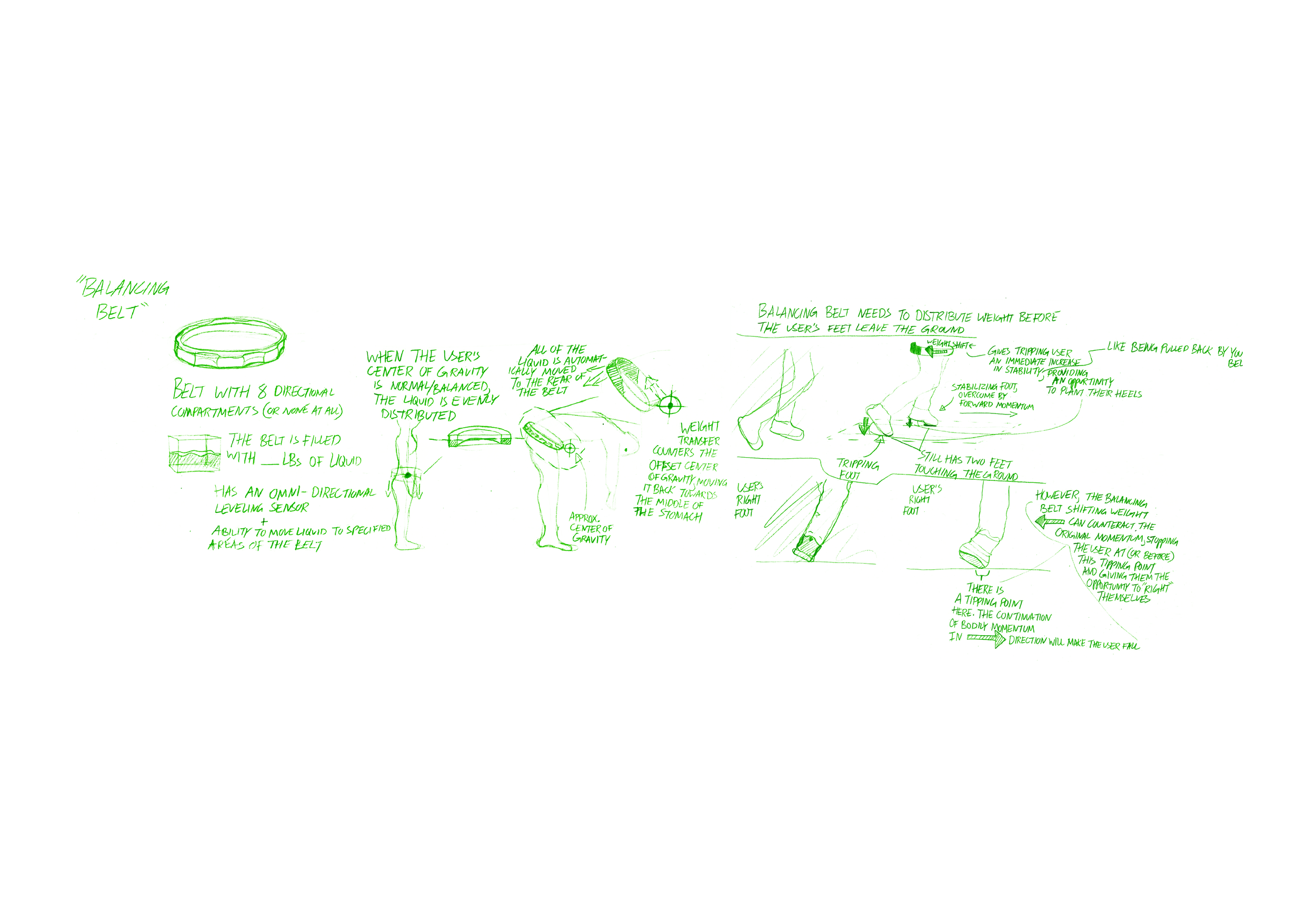
Idea 1: balancing belt
To begin ideating, I went through the motions of falling myself, thinking throughout the process about what force I would want to act on me to make me feel more balanced. My thoughts went first to a counterweight, akin to someone pulling on the back of shirt to stop me from falling forwards. This solution turned into a wearable belt concept, in which the belt would contain a mass, imagined as a dense liquid, that would be sent to the part of the belt necessary to correct for imbalance. For instance, if the user was falling forwards, mechanisms in the belt would send the liquid to the back of the belt, and this rapid weight shift from front to back would work to cancel out the forward momentum, giving the user a moment of control from which they could use their muscles to return fully to their feet.

Idea 2: Artificial Leg
This concept was inspired by the Syracuse winter. I had been mulling over a solution to falling when I began to walk down my steps, coated in a thick layer of ice, to get to class. Cautious with every step I was taking, I thought in that moment: What do I wish I had right now? The answer was a sort of kickstand, an additional leg to stabilize me, making me more tripod than biped. However this vision went past carrying a cane. I wanted something automatic, something that could detect where stability was needed and deploy itself accordingly.
In my first rendition, the artificial leg was made manageable and compact by being made up of telescoping parts, which would rapidly extend during deployment.
My second iteration had the artificial leg hanging by the user’s side freely, as if it were hanging from a belt loop, and moving along a belt-device on the user’s waist to anticipate and respond to imbalance.

discovery
Unhappy with my concepts up to this point (the counter-weight needed for the balancing belt would be too heavy)(the artificial leg would send impact force up to the users waist), I went deeper into research to look for answers and inspiration.
Buried deep in the internet I found a study from 2010 in which a flywheel system, known in this case as a “reaction wheel” was used to correct for imbalance in people walking on a balance beam. The wearable system, a sort of plastic corset with a large flywheel mounted on the lower back, used a sensor to detect which way the user was leaning while they walked a balance beam. Acting on this information, the reaction wheel would spin in the opposite direction of the user’s lean, and this torque from the reaction wheel, applied to the user’s body, would pull the user back to a balanced, upright position.

Idea 3: flywheel belt
I first looked at number and orientation of flywheel-motor units. The minimum number of wheels needed for coverage on all axes was 3, so that was a good starting point. Looking at the balance beam study I was referencing earlier, it appeared that the flywheels needed to make this belt functional would be pretty large. My first improvement on the concept was using a 4-wheel setup. 4 flywheels accounts for the minimum of 3 needed for full coverage, and situating the wheels directly across from each other in pairs allows for the force-output needed on an axis to be split between two smaller sized wheels, producing the same amount of total torque as one large wheel, if not more.

Zooming in: Unit Development
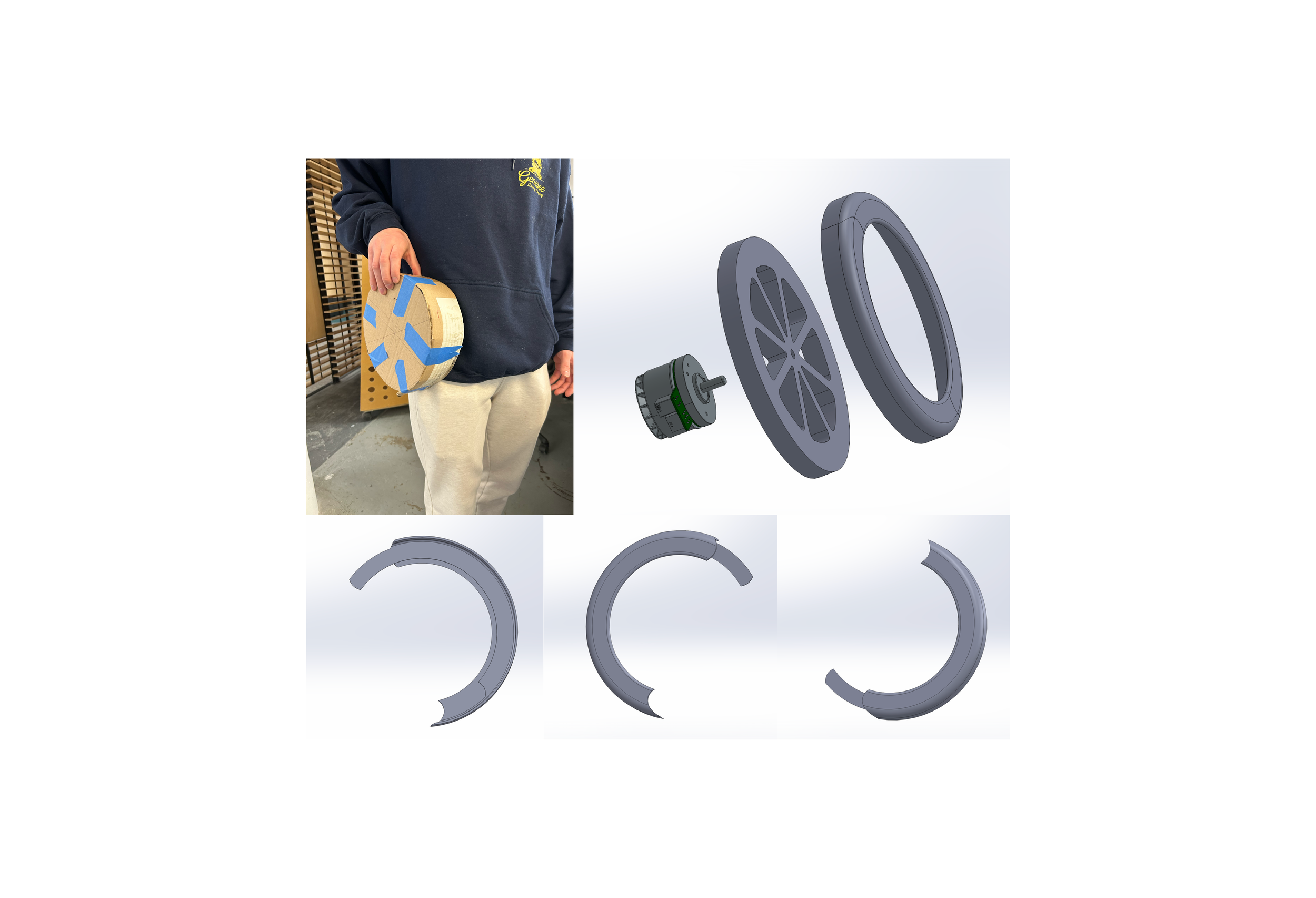
Operating with the understanding that each unit would at a minimum be composed of one motor behind one flywheel, I worked on figuring out what the housing for one of these units would look like. I had envisioned that the extra room behind the flywheel would serve as storage room for battery and computer components. In this process, I made a development on the flywheel design, opting for a spoked-wheel design instead of the traditional solid disc design that is associated with flywheels. This was done for weight distribution reasons that I expand on later.
I ended up focusing my attention largely on the front-facing aesthetics of the casing design. I took inspiration from the concept of yin and yang, representative of balance, to divide the housing in half. Additionally, I created a window opening where a clear material would be placed to give onlookers transparency into what this device is and mitigate potential confusion and fear.
Prototyping
I created simple cardboard models at decreasing sizes, starting at a 12 inch diameter, to have classmates attempt to move their arms, access their pockets, and sit down comfortably with the model on their hip. An 8 inch diameter model is where users stopped mentioning discomfort, so I moved forward with 3D modeling at this size to maximize the produced torque.
After modeling and 3D printing, I realized that I would not be moving forward with the yin-and-yang-inspired design of the housing. This decision came not only from a failure of the slot and tab system, but also a realization that if I could hide any assembly indicators, such as gaps between parts or visible screws, that I would prefer to do that to give the device a sleeker and less industrial look.
Zooming OUt: Product Considerations
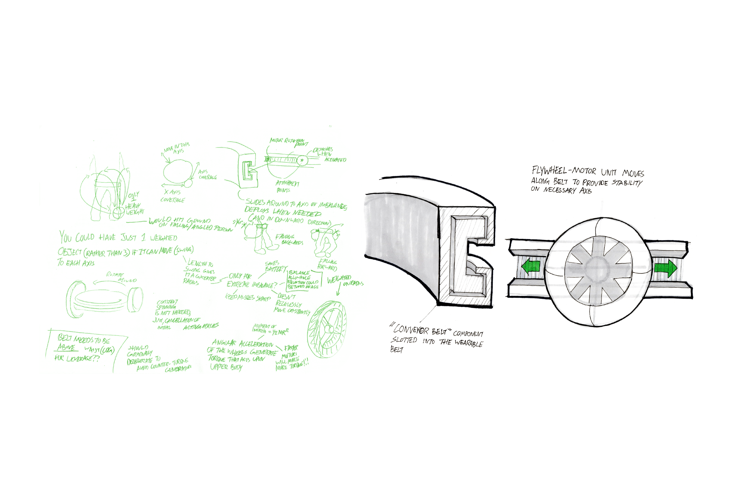
Out of the previous development process came an additional ideation stage in pursuit of a way to reduce the amount of motors and flywheels needed, as weight of the overall device came up as a concern.
The primary concept that came out of this ideation was a similar wearable belt device, however with only a single motor-flywheel unit. This unit would use a sensor to know what axis it needed to apply torque to, and move around the belt using a sort of conveyor belt system to orient itself correctly. While the weight created by flywheel-motor units would be at its minimum, the increased complexity of this device could lead to a bulkier and potentially heavier overall product.
Design Direction: Maximalism
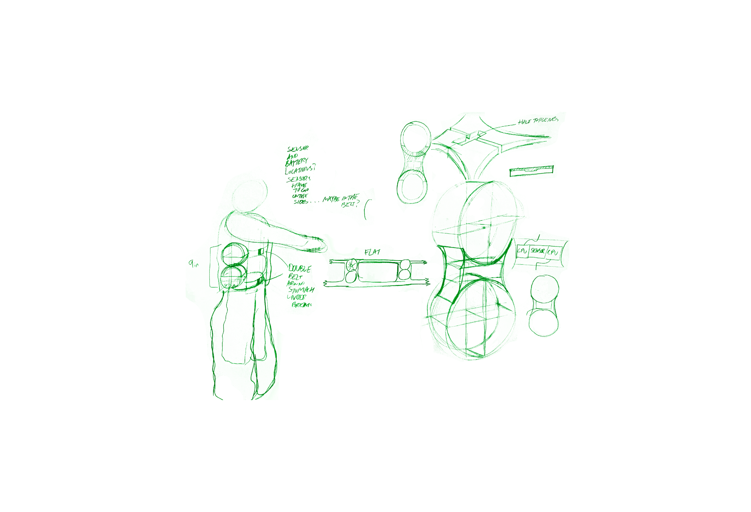
At this point in the design process I had emailed many physicists at Syracuse University, but had not yet heard back from any of them. As a result of this situation, I took a maximalist approach in developing my next iteration of the balancing device to ensure it would produce enough torque to function properly. Looking to get as much power out of the device as reasonably possible, and factoring in new feedback that 8 inch diameter flywheels were far too big, I shifted the device from a belt wearable to a torso wearable to allow the user to have a greater ability to carry the weight of the device, and to give the device more surface area for additional motor-flywheel units.
In this process, I made the decision to focus primarily on forwards and backwards movement, which are the most common directions for a person to fall. This reduced the amount of units necessary in the wearable, decreasing overall size and weight, while still tackling the problem effectively.
Torso Wearable
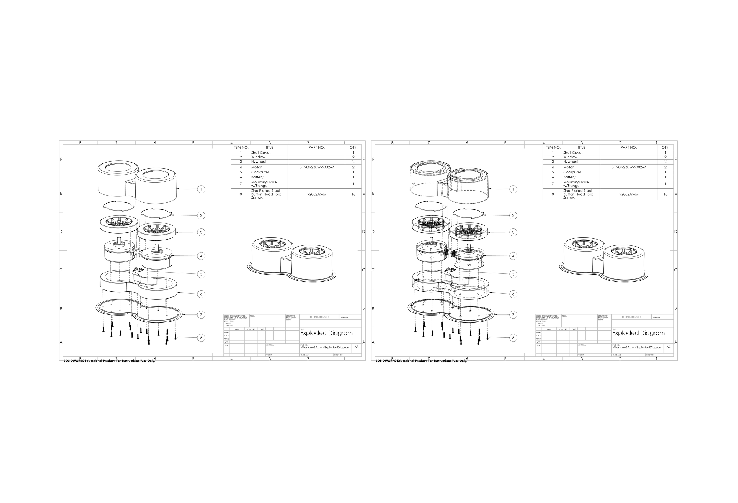
The torso wearable concept culminated in a fully fleshed-out, SolidWorks modeled design that focused on compacting its components as much as possible under the constraint of its largest component, the 4.5 inch diameter flywheel. In scaling down each wheel to roughly half of its original size, I became concerned about torque output, and looked for a more powerful motor, coming upon a 3.54in diameter EC 90 flat, brushless motor that could produce 1020 mNm of continuous torque.
The pair of double-motor units, with one full unit on the left side and another on the right side of the body, were designed to run independently. Using up the negative space created by the difference between the circumference of the motor and circumference of the wheel, I designed a custom 48v battery that wraps around the motor components and includes a recessed area between the motors to house the computer components, such as the gyroscopic sensor, that are used to direct the motors.
The shape of the shell housing that encloses each unit was designed with the idea of being compact and sleek, which ended up looking relatively plain as a cylinder with a filleted top edge. The top portion of the shell has slot-and-twist features to accommodate clear window lenses. The bottom component of the unit is a mounting plate with a flange. All of the components are attached to the mounting plate with screws. The flange allows for the entire unit to be sewn into the softer materials of the wearable component that it will be attached to. The unit would first be fully assembled, and then sewn onto the wearable component afterwards.
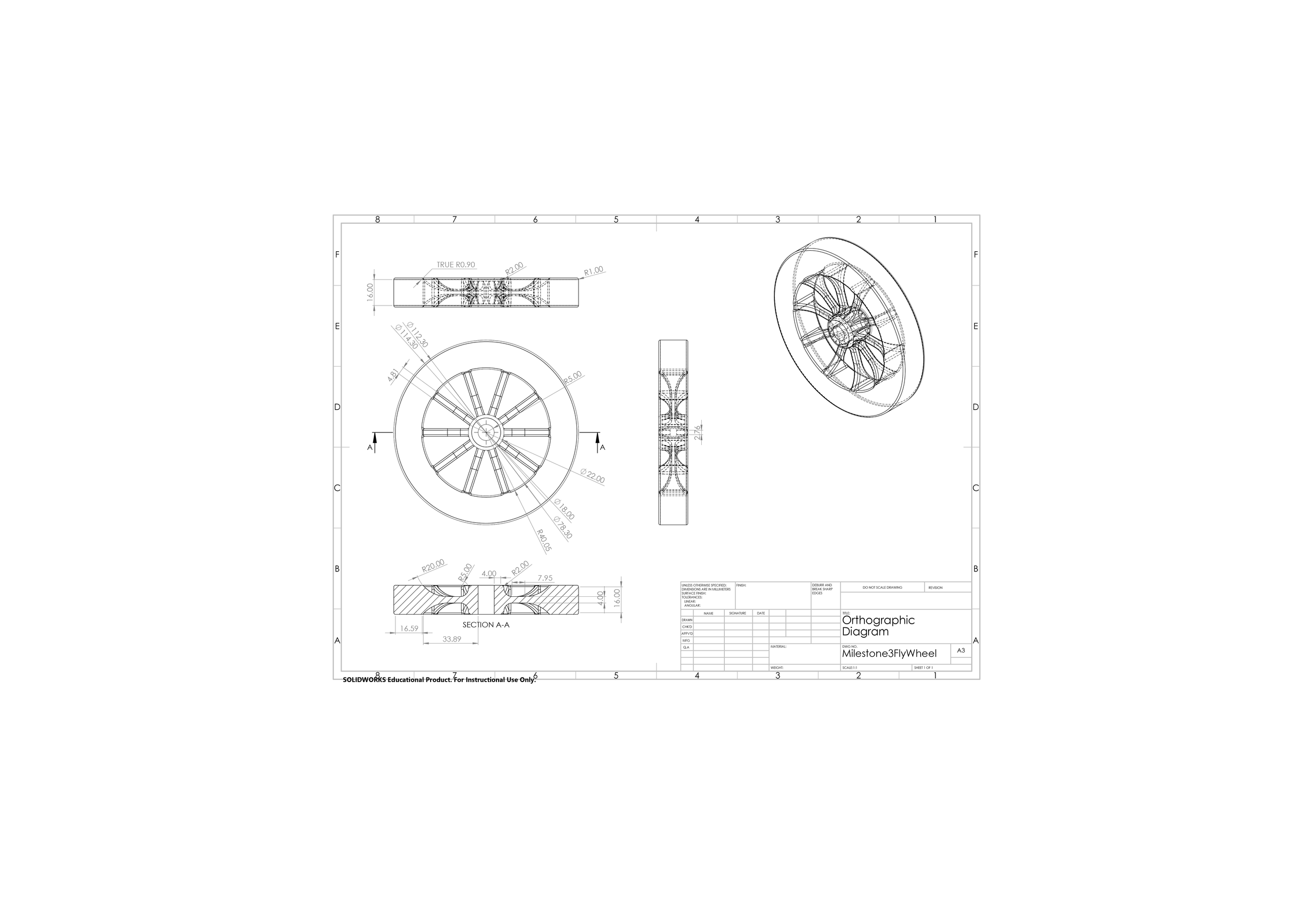
Flywheel Design
I redesigned the flywheel to be intentional in its visual communication to the user, and onlookers, of the balancing device.
Distributing weight towards the outer edge of the flywheel makes that weight more effective in producing the torque that will act on the body. There are pre-existing flywheels that are designed to have their weight concentrated around their outer edge, however, these flywheels are typically designed to maintain a solid appearance with a mostly undisrupted surface. Designing the flywheels to have spokes creates a visual communication through the spinning of the spokes and gaps, indicating movement and the speed of that movement.
The spokes are filleted differently when reaching the center versus the outer portion of the flywheel. Their form communicates that the weight of the wheel is increasing as it moves away from the center towards the outer edge. The thinness of the spokes enabled by this filleting also allow for the spokes to be very light, making the weight of the outer portion of the wheel proportionally much greater in regard to the overall weight of the flywheel.
Proving the concept
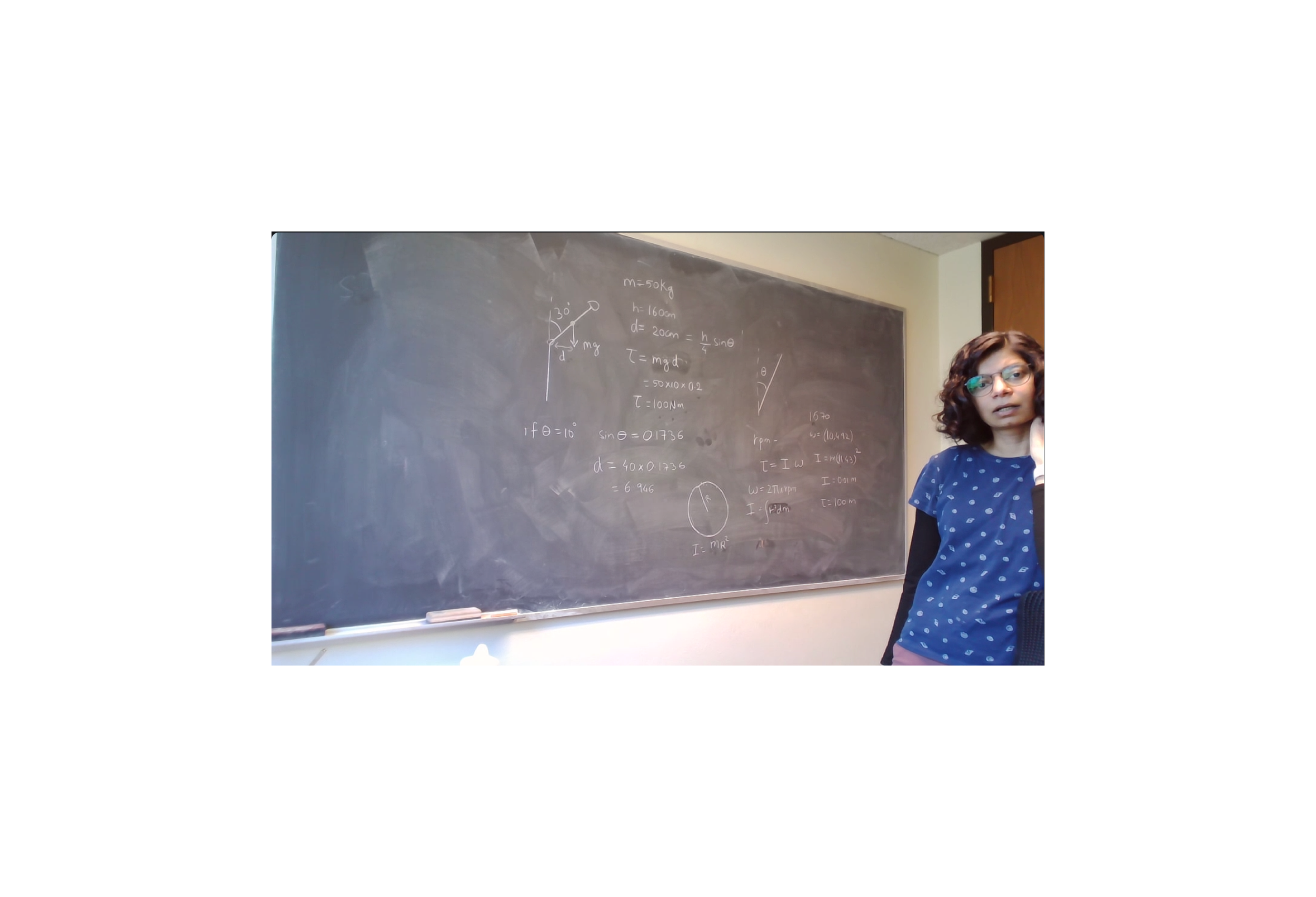
The first physicist to get back to my emails was Syracuse University Professor Dr. Nidhi Pashine. She met with me on a Zoom call to discuss the specifications that my design would need to meet, pertaining specifically to the motor and flywheel components, in order to be effective in preventing people from falling.
What we found was an immensely pleasant surprise. Calculating for a person of approximately average height and weight, 5'4 140 lbs, who is 30 degrees into falling, we plugged in the values of the powerful motor that I had researched and the 4.5 inch diameter flywheel to find the how much the flywheel would need to weigh to be able to return the user to a fully upright position.
What we found was that a single 4.5 inch flywheel would only need to weigh 2.2 lbs (1 kg) to accomplish this feat. In the case of my design, in which flywheels are employed on two sides of the body to create directional stability, this meant that each wheel in a two-flywheel wearable only needed to weigh 1.1 lb (0.5 kg).

Returning to the Belt
Finally having the physics work calculated was revolutionary to my design process, and knowing that I only needed two small flywheels allowed me to abandon the maximalist torso wearable concept and return to designing the device as a belt wearable.
Having accounted and designed for so many variables and human factors throughout this entire design process, I was able to return to the belt concept with strong ideas of what demands the wearable needed to meet and how it could do so effectively. The main considerations were the form of each motor-flywheel unit, assembly, and weight support.

Current Design
The philosophy when creating the current design of the automatic balancing device was to make a product that is grounded in reality rather than idealistic conceptualism. This design uses currently available parts (ex: ec90fl-260w-500269 motor) to showcase that, as evidenced by research and mathematical proof, this device could be made and used today.
Carrying weight
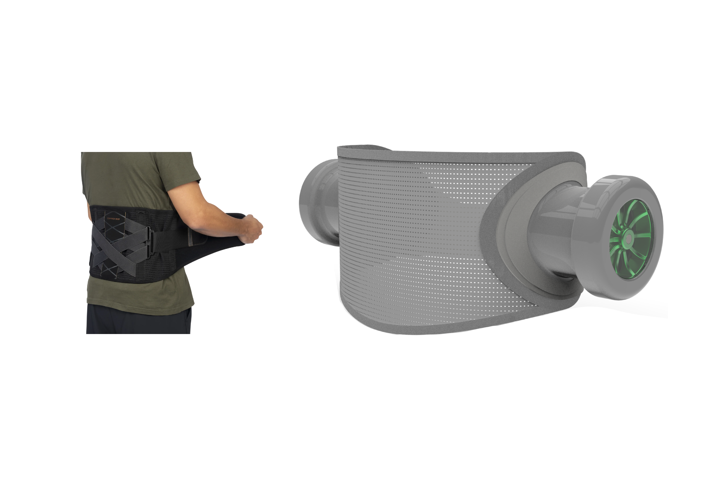
Thinking of how an elderly person, someone with likely lessened muscle mass and a frailer frame, would carry the weight of any kind of assistive device, I knew that the wearable component of the balancing device would need to make thoughtful considerations for weight. Looking for parallels to my product, I noted that police officers traditionally carry a lot of their gear on their belt. When I interviewed our Syracuse Department of Public Safety officers, they largely reported experiencing lower back pain and discomfort as a result.
With this knowledge, I looked to existing back support products and found the Copper Fit X Back Brace, which wraps tight around the waist using the elasticity of a thick mesh with Velcro straps for a snug fit. The X Back Brace is further secured by secondary Velcro straps attached to a lumbar panel. I took inspiration from the mesh and form of the X Back Brace for their snug fit and support, but omitted the lumbar panel from my design as there are negative effects that come from frequently wearing such a structurally supportive back brace.
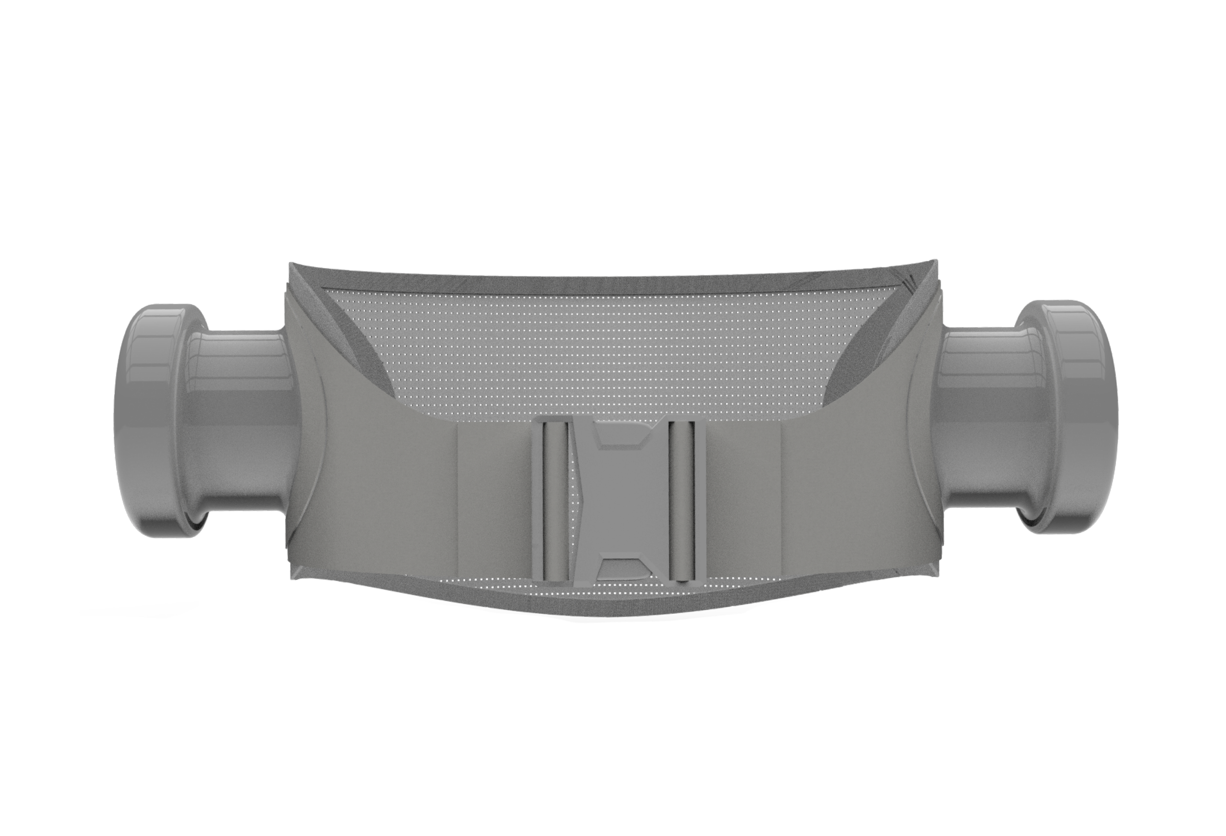
Easy equip buckle
When designing the fastening mechanism to be used for putting on the belt, I harkened back to the guiding principle that I had established earlier, that the device should be easy to put on in a hurry.
The X Back Brace that I had referenced for the rear portion of the belt secures itself by wrapping around the user. There are several downsides to using a wrapping system. Notably, an exertion of strength is required to tightly wrap the belt each time it is put on, but more importantly, if the user wraps the belt while sitting, they will need to take off and adjust the belt again while standing, creating a moment while they are on their feet and without the aid of the device if they were to fall.
What the side release buckle accomplishes is an effortless, quick, and pre-adjusted fit for the user. Pushing the two ends of the buckle together takes less effort than tightening any kind of adjustment mechanism. The user can release the buckle while sitting, allowing it fall flat by their sides, and when they are ready to stand up, can click the buckle back together without worrying about adjusting fit. In a hurry, locating the two sides of the buckle and clicking them together is a straightforward endeavor.
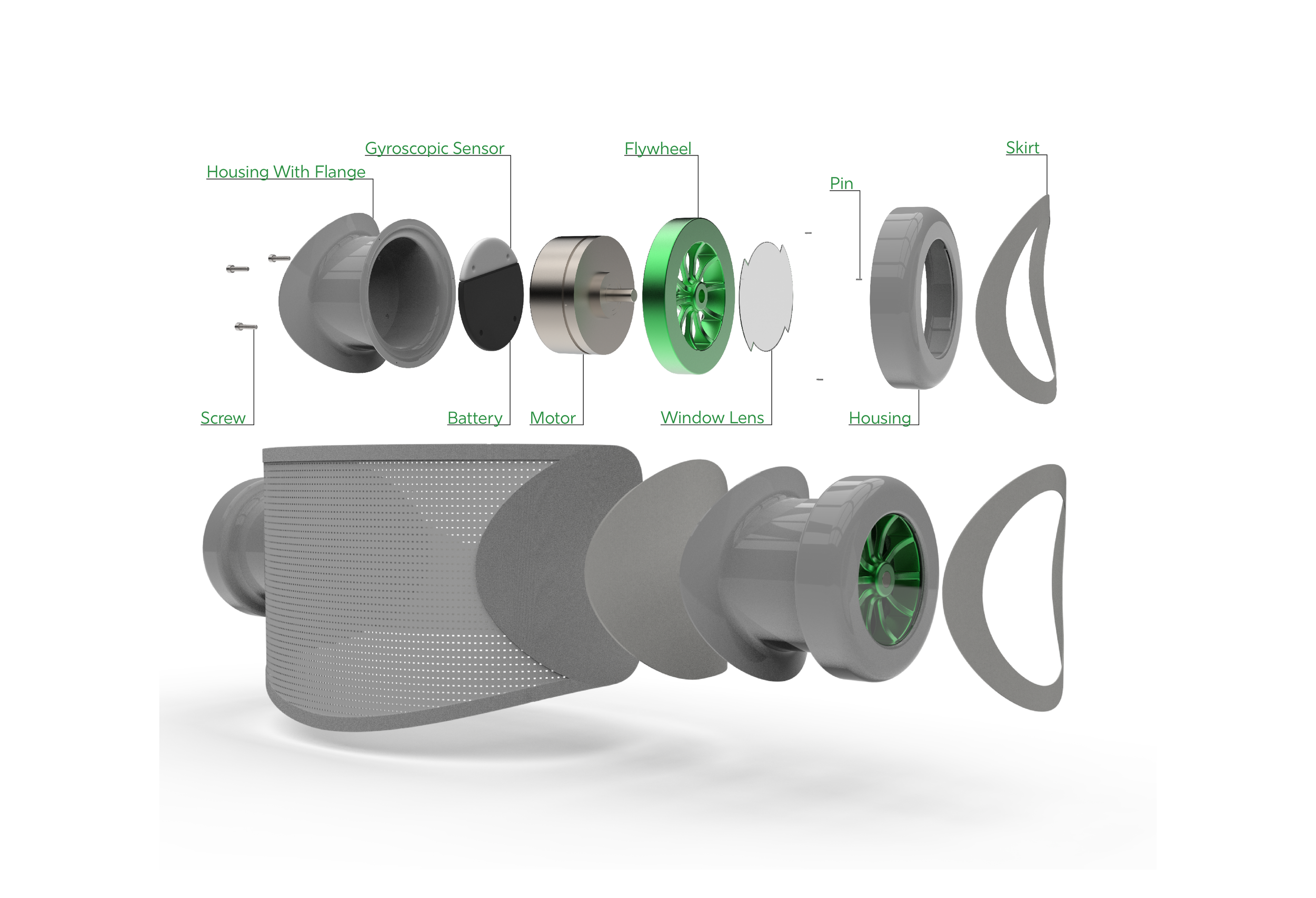
Assembly
Each unit contains a battery, gyroscopic sensor, motor, flywheel, and window lens.
Each unit is attached to the wearable components using industrial sewing, layering the flange of the unit’s housing over the front portion and rear portion of the wearable. A fabric skirt is sewn over the flange to give a finished and cohesive look to the end product.

Looking forward
Having filed for a provisional patent, I am invested in developing this product as I believe that it is realistically actionable and, if carried out properly, will have a major positive impact on the lives of many.
The next steps for this product involve building a functional model for testing as well as going through R&D processes to create custom fine-tuned components for this device that are smaller and more powerful. Funding for R&D and custom components would allow for the visual design of this device to change entirely, becoming sleeker and more appealing to use.