
The Ramp Race
The yearly SUIID Ramp Race asks third year students to use CAD modeling and fabrication skills to produce a race car that will speed down a steep ramp and then up a counter-ramp, competing in the categories of: Vertical Jump Height (how high the car goes when flying off the counter-ramp), Accuracy (how close the car stops to a target decal on the counter-ramp), Construction, and Style.
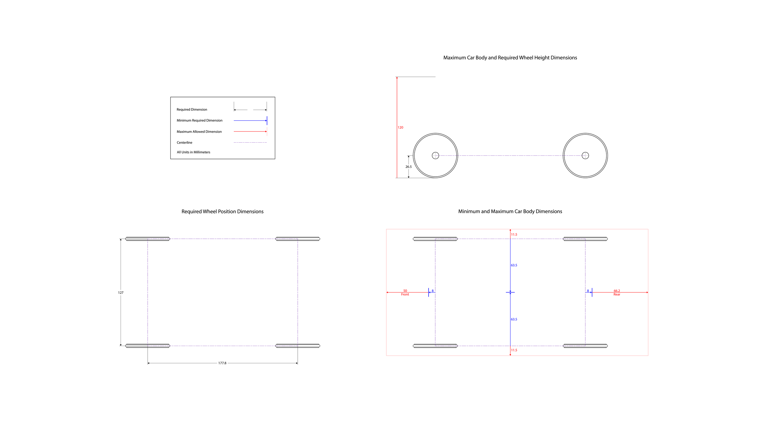
The car is required to contain at least one component that is vacuum-formed from a CNC-fabricated model, one laser-cut component, and 50-inch diameter wheels. The entire assembly must be no more than 575 grams in mass and within the dimensions of 310mm(L)x150mm(W)x120mm(H) in addition to the other requirements shown below.
Building a base
Having awaited the Ramp Race for years at SU, I had strong ideas of what I wanted my car design to accomplish
Visually interesting - deviating in form from the templates/example materials
Tuned for performance - aerodynamic, form following function
Intentional Design - every part added onto the car is thoughtfully implemented and not tacked on
Through questioning senior students and tracking down past projects, I learned that it was beneficial to include: A structural brace to keep joined parts secure and aligned and an easily detachable upper body to absorb impact and allow for easy internal access for alterations and repairs.
References
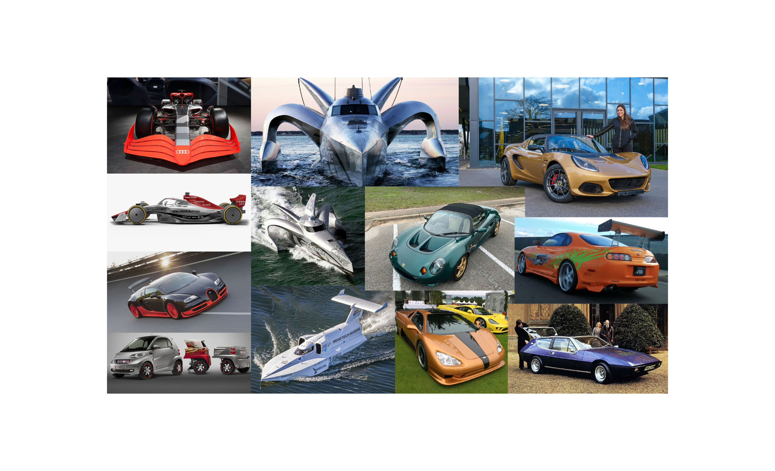
Understanding the attributes of some of the fastest cars built for the road and the track.
Going past cars, looking at the unique forms of the fastest boats to discover unconventional ways to achieve aerodynamic success.
Lotus Cars - Known for producing the cars with premier handling and remarkably low weights, Lotus is able to get the most out of every pound of their vehicle. With every ramp race car constrained by the same weight limit, I can take inspiration from Lotus to apply my car’s weight more effectively to increase the performance of the vehicle, giving me an edge over the competition.
Aerodynamics Research
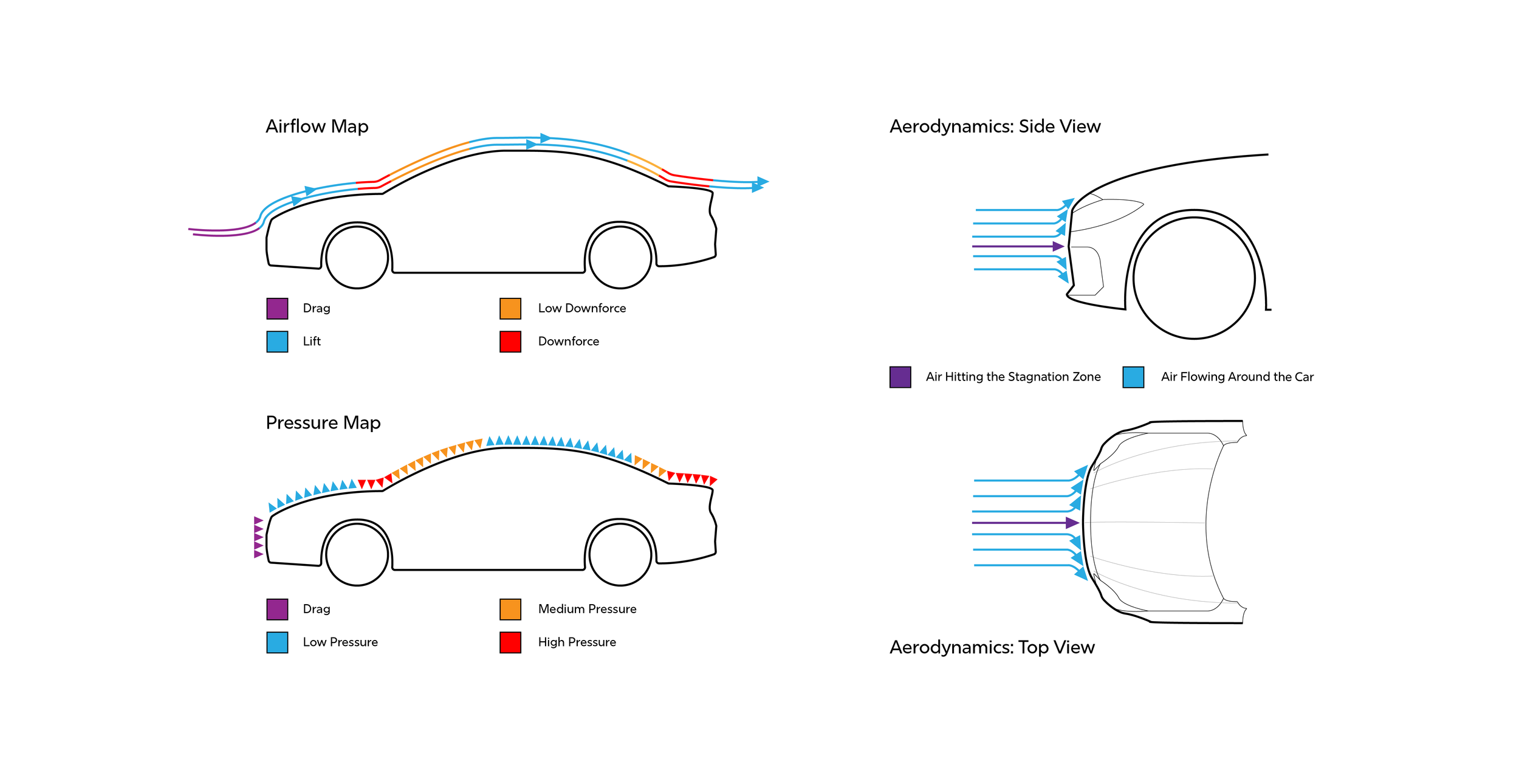
Designing for performance meant doing in-depth research into aerodynamics to inform the overall form of the car.
What I found is that having a greater surface area for creating downforce will more effectively apply the weight of the car to the track, increasing speed when going down the ramp. Additionally, the form of the car should primarily curve in ways that send airflow around the vehicle to avoid creating stagnation zones which will slow the car down.
Working Concept
Not thinking about the dimensional limitations, I created a concept car to embody the design ideology that would later be converted into a practical design.
Features of this concept include intentional air resistance pockets to straighten the car, a triple ‘spearhead’ form to cut through air resistance, a wide rear surface to maximize downforce, and even weight distribution across the widest part of the car.
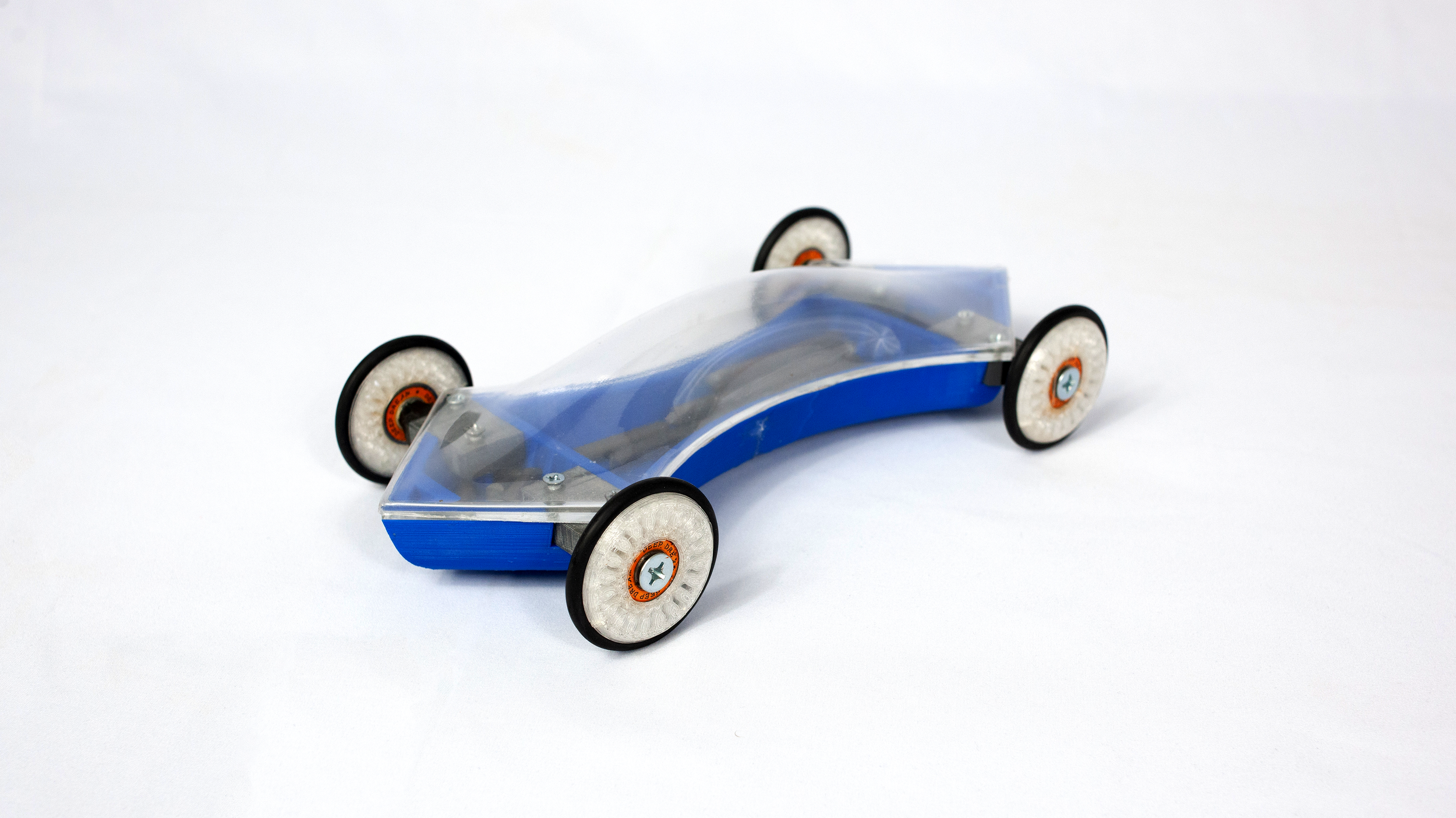
Philosophy for Final Design
Reduction: Working under the structure created by following the minimum requirements. The car is as slim as possible except when it widens out to meet the wheels. The main components of the car are housed underneath the required height of the wheel axles.
Aerodynamics: The sleek form of the car focuses on breaking air resistance with its sharp front edge and then distributing air flow around the sides of the vehicle, smoothly under the flat bottom of the vehicle, and purposefully over the downforce-optimized contours of the vehicle’s upper shell.
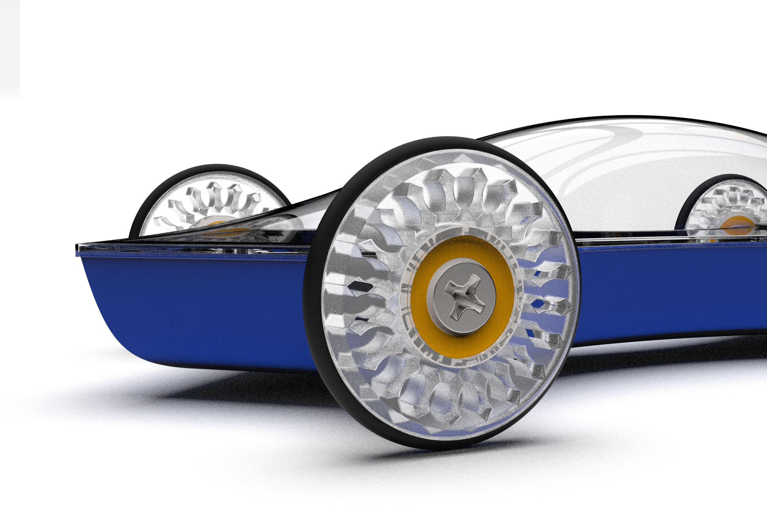
Construction: The laser-cut plate screws down onto the 3D printed underbody, which houses the wheel axles and weight system, sealing away and securing all of the under-components in place. The vacuum-formed upper shell pressure-fits onto this assembly to give it a more aerodynamic form.
The required components
The wheels and axles remain unchanged from the dimensions that were given as part of the assignment
The laser-cut center plate deviates heavily from the rectangular center plate templated in the assignment directions. Its new design dictates the shape of the car body, which as a result is sleeker and lighter than the default, freeing up more weight to be incorporated into the weight system.
The vacuum-formed upper body component was designed to maximize downforce to more effectively apply the weight of the car to the track. Having flat surface area at the front and back of the car’s upper body means capitalizing on the widest parts of the vehicle to produce this downforce. Additionally, this part is pressure-fit onto the car body, allowing it to pop off to absorb impact on collision.
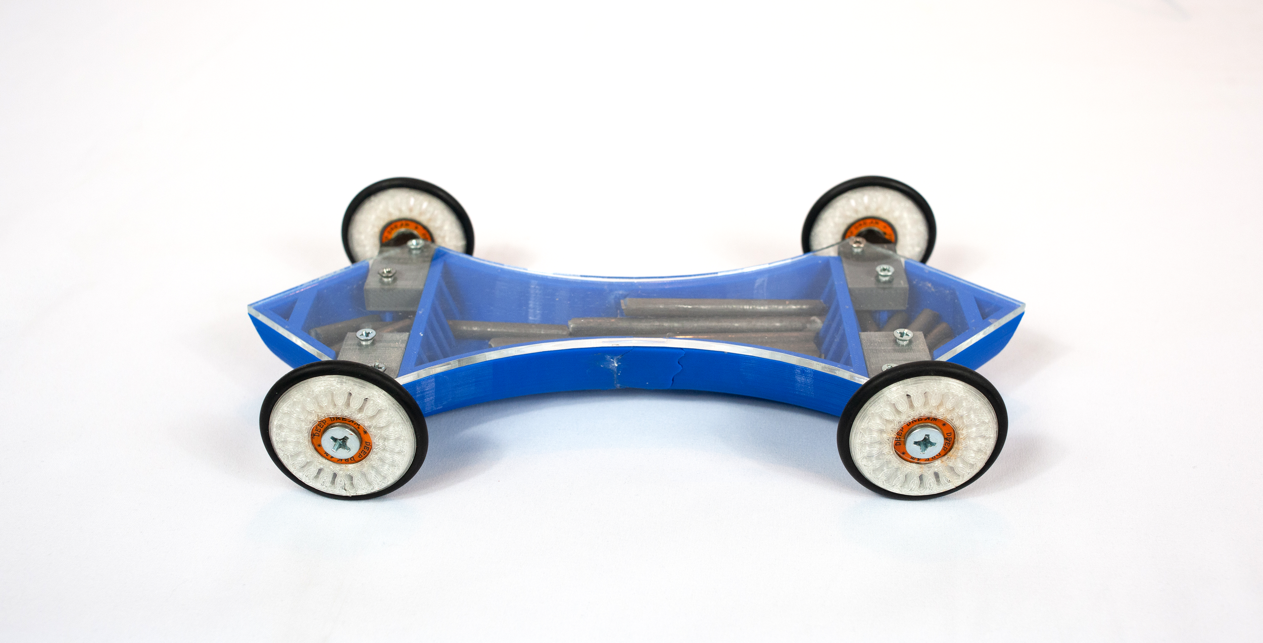
The Underbody
The underbody is the primary component of the car
The underbody provides a rigid structure for car body assembly. It has notches with flat walls to securely align the wheel axles against.
The interior of the underbody has been compartmentalized to create a small-unit weight system using BBs that can be fine-tuned for weight distribution. There is a “spear tip” weight compartment at each side of the vehicle, with the idea that weight will want to take the straightest path down the ramp and will act as a self-righting measure.
Modeling considerations
Screw columns rise out of the floor of the underbody to meet the bottom face of the wheel axles, providing more than enough material for screw threads to dig into to make a strong connection
Added gussets to the SolidWorks model to support the screw columns and stabilize the axle-alignment wall during 3D printing to prevent warping.
The underbody is split into two parts due to the size of 3D printer that I had access to. To make the joining of these two parts easy and precise, I designed a sort of tongue and groove joinery.
The Test Race
Putting together a quick prototype of the car concept for testing, I did not yet have the underbody component finished, and instead used the traditional body structure of two acrylic plates, but with my custom-shaped plates instead.
To test the car with weight, I left the vacuum-formed upper with additional height and secured BBs on top of the acrylic plate inside a dome of plasticine.
The car performed well in terms of speed but had some issues driving straight. This was not a worry as the underbody component was designed to correct that issue.

Re-designs
Wheel weight was reduced in a stylistic way with car-shaped silhouette cutouts.
The upper component was trimmed to have a lower lip height for a perfect fit.
The weight system had to be changed last minute, after pre-race testing, from using BBs to using cut metal bars because:
Impossible to install wheel axles with BBs tightly packed into the same space
Loosely packed BBs move backwards on the counter-ramp and counter the momentum of the car
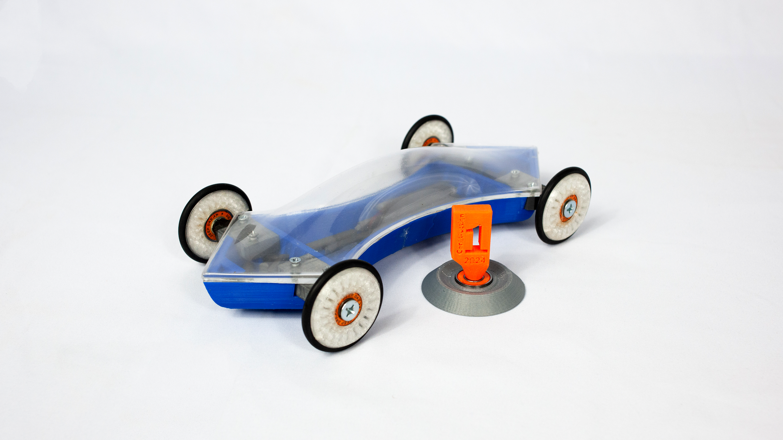
Outcome
The car was awarded Best Construction
The car did not end up being as fast as anticipated. This can be attributed to the aforementioned weight system issue, but also largely attributed to a rushed job degreasing and re-lubricating ball bearings prior to the race, which if done properly would have significantly improved speed.
No parts of the car broke, were damaged, or failed during the race.
What I’M Doing Next
Performance testing the functional prototype, allowing me to identify, and design solutions for, performance issues
As a result, I will likely rework the weight system, either designing it to better accommodate the BBs, or instead pivoting to designing intentionally for use of metal rods.
Additionally, I will focus the weight system design on weighting primarily the rear of the vehicle, which positions the weight higher up on the ramp and increases momentum.